Wednesday 11 November 2020

ISIS Series- Part 8: ISIS Configuration


Configuration

In this lab we will configure IS-IS to carry IP routes. The IS-IS Lab Files include the initial and final configs for the topology.

The router R2 will summarise the IP’s of the loopback interfaces into a /22 network.

The topology is as follows:


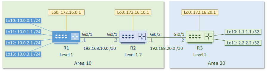
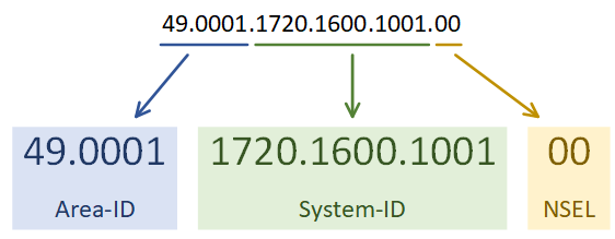
The first step is to enable the IS-IS process. Each IS-IS area uses a separete process. In the example below, the System-ID uses the IP address of Loopback 0 in the NET value. This could be any value, but reformatting a loopback IP makes troubleshooting easier.

The use of passive-interface is the same as with any other routing protocol.

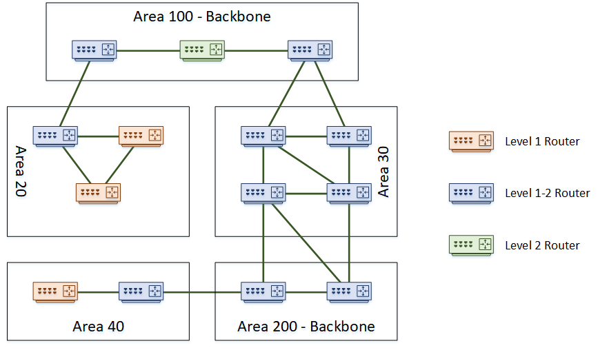
The first IS-IS process on Cisco routers are set to Level 1-2. All later processes are Level 1 by default. Change this with the is-type command.

Following this, enable IS-IS on an interface.


[rtbs name=”isis_intro-configure”]


Show clns neighbours 

confirms that neighbour relationships have been established.

Show isis database 

shows the LSDB. 

This is router reachability information.

Show clns interface 

shows the IS-IS settings for the interface.


[rtbs name=”isis_intro-adjacency”]


We can see that IS-IS has learned routes, and installed them into the routing table.


[rtbs name=”isis_intro-routingtable”]


Under the IS-IS process, a summary address can be configured.

If a default route were required, it could be advertised with default-information originate.


Configure Summarization

R2(config)#router isis 
R2(config-router)#summary-address 10.0.0.0 255.255.252.0 level-2


You can see that R3 is now learning the summary address, rather than each individual network.


Verify R3 Routing Table

R3#show ip route isis
Gateway of last resort is not set

      10.0.0.0/22 is subnetted, 1 subnets
i L2     10.0.0.0 [115/20] via 192.168.20.1, 00:03:15, GigabitEthernet0/1
      172.16.0.0/32 is subnetted, 3 subnets
i L2     172.16.0.1 [115/20] via 192.168.20.1, 00:19:51, GigabitEthernet0/1
i L2     172.16.10.1 [115/10] via 192.168.20.1, 00:19:51, GigabitEthernet0/1
      192.168.10.0/30 is subnetted, 1 subnets
i L2     192.168.10.0 [115/20] via 192.168.20.1, 00:19:51, GigabitEthernet0/1


Sunday 25 October 2020

ISIS Series- Part 7: ISIS Adjacencies


Adjacancies


IS-IS uses Protocol Data Units, or PDU’s to communicate. This is like a packet in OSPF terminology.

An IS-IS Hello PDU, or IIH, is like OSPF hello packets. Routers exchange IIH’s to form neighbour relationships, and share area addresses.

IS-IS sends IIH PDU’s at layer-2, using a multicast MAC address. This is why there is only a need for a single address (the NET or NSAP) per router. Addresses aren’t required per interface. This also shows that IP addresses on interfaces are irrelevant to IS-IS.

Level 1 routers need the Area-ID to match. Additionally, level 2 routers will ignore IIH’s from Level 1 routers. Authentication and network type must also match for neighbours to form.

Level 2 and Level 1-2 routers do not need level 2 IIH’s to have the same Area-ID


A Link State PDU, or LSP, contains routing information, and is flooded to neighbours. LSP’s are like OSPF’s LSA’s. There are two types of LSP’s; Level 1 LSP’s and Level 2 LSP’s. Level 1-2 routers send and receive both types.

The LSP contains a header and TLV fields. The TLV fields contain the information that is being advertised, such as IP routes. Extra TLV’s contain other data, like neighbour information, and authentication information.

When there are network changes, the router floods LSP’s out. Other routers receive these LSPs, and used them to build their Link State Database (LSDB). IS-IS is more efficient at this than OSPF. It combines several networks into an LSP, rather than sending many small LSA’s. This adds to the scalability of IS-IS, as more routers can exist on the network without over flooding.


When IS-IS is on broadcast media, one router is the Designated Intermediate System, or DIS. The DIS will flood LSP’s out, instead of having all routers flood the segment. This is like the Designated Router in OSPF.

Routers hold an election to select the DIS. The router with the highest priority on the segment wins the election and becomes the DIS. If there is a tie, the router with the highest MAC wins. DIS uses preemption, so if a router with a better priority comes along, it will become the new DIS.

There is no backup DIS. This is different to OSPF, which has a BDR role.

Friday 11 September 2020

ISIS Series- Part 6: ISIS NET Value


NET Value


A Network Entity Title, or ‘NET’, is an address that identifies the router. It consists of the router’s system ID, and the area address. A NET is a type of NSAP address.

Each router’s NET is unique. They can be anywhere from 8 to 20 bytes long, but are often only 10 bytes.

An example of a NET is 49.0001.1720.1600.1001.00. As shown in the example below, this represents the Area-ID, System-ID, and NSEL values.


The address is a series of HEX values, separated by dots. The Area-ID is variable in length, but must be at least one byte. It is often a three-byte value. The first byte (49 in this example) is the AFI, or Address Family Identifier. This is often set to 49 for IS-IS, which is the OSI value for private addressing. 0001 in this example refers to area 1.

The System-ID needs to be unique within the area, but may overlap in different areas. Combining it with the Area-ID makes the entire address unique. In Cisco’s IS-IS implementation, the System-ID is 6 bytes.

The NSEL is the N-Selector. This has a special meaning in the OSI stack, but for IS-IS this will always be set to zero.

Tuesday 18 August 2020

ISIS Series- Part 5: ISIS Inter-Area Routing


Inter-Area Routing


To route a packet outside an area, a level 1 router sends the packet to the nearest level 2 capable router. The nearest router is always used, regardless of the destination. Level 1 routers don’t have enough information about other areas to make a decision.

When the packet reaches the level 2 router, it gets forwarded across the backbone to get to the correct area. It is then passed on to a level 1 router in the area for local delivery.

To optimise routing, it is possible to leak routes from the level 2 database into the level 1 database. This technique prevents suboptimal routing outside the area. When leaking routes, they have a flag added. This prevents advertising them back into the level 2 database elsewhere.

When routing the packet within an area, the routers use the System-ID of the router for delivery. When routing packets between areas, the Area-ID is the address. These addresses are part of the NET Value.

Tuesday 7 July 2020

ISIS Series- Part 4: ISIS Router Levels

Level 1 routers will only share routing information with other Level 1 routers. This makes them stub routers. In the topology above, area 40 is a stub area. Routing within an area is Level 1 Routing.

Level 2 routers will only share routing information with other level 2 routers. These routers track routing information between areas. This is Level 2 Routing.

Level 1-2 routers are special, as they take part in both level 1 and level 2 routing. They connect areas together, which makes them the perfect place to use summarization. These routers maintain a separate database for level 1 and level 2 routes.

Areas can connect to each other, or a dedicated backbone area could be used for transport. Backbones consist of routers that do level 2 routing, including level 1-2 routers. They won’t have hosts or Level 1 routers connected.

A small network does not need to have a backbone at all. It can start as a single area with only level 1 routers. As an alternative, it can be all level 1-2 routers, to make it easier to add a backbone later.

A domain is an entire IS-IS system under common administration. This is like the concept of an Autonomous System in BGP.

Friday 19 June 2020

ISIS Series- Part 3: ISIS Areas


Like OSPF, IS-IS uses areas. Areas can be either a backbone area, or normal area. To support this concept, a router may be one of the following types:
  • Level 1 – A router in a normal area that does not connect to another area
  • Level 1-2 – A router in a normal or backbone area that connects different areas
  • Level 2 – A backbone router that does not connect to other areas


The topology below shows an example of a network with several areas.

There are a few interesting points in this topology. Notice that the backbone area is not restricted to being ‘area 0’ like in OSPF. In IS-IS, any area number can be the backbone. Also notice that it is possible to partition the backbone. In this topology, both area 100 and area 200 are the backbone.

A further point of interest is that area boundaries are not on the routers themselves. Rather the area boundaries are between routers. This is different to OSPF, where an ABR or ASBR router is the boundary.


Saturday 9 May 2020

ISIS Series- Part 2: ISIS Components


As the history of IS-IS is in the OSI stack, some of the components are a bit different to what we’re used to in the TCP/IP world. Let’s clear up a few of the terms.


An IS is an Intermediate System. This is the ISO name for a router, and how IS-IS gets its name. It is communication between intermediate systems, or routers.

An ES is an End System. This is a device on the network, such as a server or workstation. In the original specification, an ES would take part in IS-IS. It would have no need for DHCP or FHRP, as it would already have a local routing table.

CLNS (Connection-Less Network Service) is a network service in the OSI stack. CLNP (Connection-Less Network Protocol) is the protocol that implements CLNS. If you’re more familiar with TCP/IP, this feels unusual. TCP/IP does not separate the service and the protocol in this way. This will make more sense with time.

An NSAP is a Network Service Access Point. This is a layer-3 address, for CLNS packets. This is like an IP address in the TCP/IP stack. IS-IS uses NSAP addresses for communication, not IP addresses. Again, this will make more sense as we go through the article.


TLV


TLV, or Type Length Value are the payload fields in IS-IS. The TLV fields carry routing information. IS-IS does not care what goes in these fields, which makes it protocol agnostic. This is a bit like shipping containers; The ship doesn’t care what’s in the containers.

IS-IS uses CLNS for transport. Each router has an NSAP address for sending and receiving link state information. The link state information may contain several TLV fields.

It is common to put IP routing information into the TLV’s. But any sort of data can be in there. It’s up to the receiving router to know what to do with the information.


Metric


Like OSPF, IS-IS uses cost as a metric. The specification says that this can be either a wide or narrow value. Cisco routers only support the wide metric. The narrow metric is not suitable for MPLS Traffic Engineering. The wide metric uses 24 bits for the link metric, and 32 bits for the path metric.

All links have a cost of 10 by default. This means that in a default implementation, hop-count forms the metric. It is up to the network designer to select a more suitable cost scheme.

Sunday 12 April 2020

ISIS Series- Part 1: Introduction to ISIS

IS-IS, or Intermediate System to Intermediate System, is an open standard routing protocol. ISO published the standard as a way to route datagrams as part of their OSI stack. IETF later republished the standard, and added IP route support.

There are a lot of similarities between IS-IS and OSPF. For one, both are link state routing protocols, meaning that they both build a ‘map’ of the network. They both flood link state data through the network, and build a Link State Database (LSDB). Also, they both run Diikjastra’s algorithm on the LSDB to compute shortest paths.

So, if it’s like OSPF, why use it at all? Why not use OSPF instead? Well, there are two massive strengths to IS-IS. The first is it’s scalability. It’s much easier to build large networks with IS-IS than it is with OSPF. This makes it a common choice with service providers for their infrastructure.

The second strength is its agnostic approach to the data it carries. IS-IS carries a payload of reachability data, but for the most part it doesn’t care what’s in the payload. This is what makes it useful for protocols such as FabricPath. In contrast, OSPF carries IP routes only. When IPv6 came along, it required a whole new version of OSPF (OSPFv3) to carry the IPv6 routes. No such issue in IS-IS.

Thursday 12 March 2020

Network Topologies- In context of DC


Data centers are crucial components in the functioning of modern businesses. These facilities house large amounts of data and computing resources that are critical for organizations to deliver their services. The architecture of a data center is of utmost importance in ensuring that these resources are accessible, secure, and reliable. One key aspect of data center architecture is network topology, which refers to the way in which the components of a network are arranged.

There are several network topologies that can be used in a data center, each with its own advantages and disadvantages. In this blog post, we'll explore some of the most common topologies and their applications.

Bus Topology


A bus topology consists of a single cable that connects all the devices in a network. Each device is connected to the cable through a T-connector, which splits the cable's signal. This topology is easy to implement and is cost-effective, but it can become slow and unreliable as the number of devices on the network increases. In a data center context, a bus topology is not typically used as it does not scale well.

Star Topology


A star topology consists of a central device, usually a switch or a hub, that connects to all the devices in the network through individual cables. This topology is easy to install, and faults are easy to isolate, making it a popular choice in data center architecture. However, it can be expensive to implement as it requires a large number of cables.

Ring Topology


A ring topology consists of devices that are connected to one another in a circular fashion. Each device is connected to two other devices, creating a ring. Data is transmitted in one direction around the ring, and each device repeats the signal to the next device. This topology is reliable and efficient but can be expensive to implement, and faults can be difficult to isolate.

Mesh Topology


A mesh topology consists of devices that are connected to one another through multiple paths. This topology is highly resilient and fault-tolerant as data can be rerouted if a path fails. It is also highly scalable and can accommodate a large number of devices. However, it can be expensive to implement, and the complexity of the network can make troubleshooting difficult.

Hybrid Topology


A hybrid topology is a combination of two or more topologies. For example, a data center might use a star topology for its access layer and a mesh topology for its core layer. This approach allows for greater flexibility in designing the network to meet specific requirements.

In conclusion, selecting the right network topology is critical for a data center's success. Each topology has its own strengths and weaknesses, and choosing the appropriate topology depends on factors such as scalability, reliability, cost, and ease of maintenance. Ultimately, a well-designed network topology can ensure that a data center functions efficiently, securely, and reliably, meeting the demands of modern businesses.

Wednesday 19 February 2020

Wireshark Series: Part 3- TCP and UDP


• Transmission Control Protocol (TCP):

○ TCP makes sure that the data goes to destination in a reliable manner
○ TCP sends data b/w ports which range from 0 to 65535
§ Ports from 1- 1023 are called Standard Ports. These can be Port 80 for HTTP
§ Ports 1024- 65535 are called ephimeral ports. These are randomly selected when a device needs to find an open port. Both the destination and the client need to know what port the other one is listening on to be able to transmit data between them
○ TCP communications start with a handshake to ensure both source and destination are up and ready to communicate. It checks the open port and send the sequence number so that the data is sent reliably.
○ To establish a TCP session the sending and receiving TCP applications us a process called the three way handshake.
STEP 1 - The sender send a SYN packet to begin establishment of the session. It waits
STEP 2 - The receiver replies with an ACK packet to acknowledge the SYN that it received and also sends a SYN packet.
STEP 3 - The sender sends an ACK to acknowledge receipt of the SYN from the receiver.
The connection is now set up and data transfer can commence.
○ Now to terminate a connection you can do it the graceful way which is a four way process. Lets assume that the sender is finished with data transmission and now wants to end the session, similar to logging off an application.
STEP 1 - The sender sends a FIN packet and waits for a reply
STEP 2 - The receiver send and ACK packet
STEP 3 - The receiver also sends a FIN packet
STEP 4 - The sender sends an ACK packet and the session is closed.
○ You can also do an abrupt termination by just sending a RST packet from either sender or transmitter and the session ends abruptly. For example if you are using telnet CTRL-D will send a RST to close the session.
○ In Wireshark,
§

§
§ First, we see Source Port which was used to transmit the packet
§ Second, we have Destination Port to where the packet will be transmitted
§ Next, we have the Sequence Number  makes sure that none of the TCP segments are missing and it shows the current segement no.
§ Acknowledgement Number is the sequence number of the next packet
§ Flags are after this and they can be:
□ URG for Urgent
□ PSH for push
□ RST for Reset. If the connection is halted all of a sudden by accident, then TCP  will reset the connection and stop all communications
□ SYN
□ FIN for finished
(Here, we have a FIN, ACK packet going on, so we know that this is a packet that includes acknowledgement. Also, because FIN=1, it means that it is also a finishing packet)
§ Below Flag, we have the Window Size. Window Size is the size of the TCP receiver buffer (in bytes).
§ After that, we have the Checksum

• User datagram Protocol (UDP):
○ It is a connectionless protocol used for faster transmissions
○ It does not have a start handshake and a cutoff handshake like TCP. Because of this, it helps other protocols transfer data at a much faster pace
○ In Wireshark,
§
§ It is a super small packet
○ It has 4 parts:
§ Source Port (here: 33233)
§ Destination port (here: 59329)
§ Length (in bytes)
§ Checksum


Wednesday 12 February 2020

WireShark Series: Part 2- ARP and IP

• Address Resolution Protocol (ARP):
○ First, inorder to send TCP/IP , the computer first sends out an ARP request
○ It means, the computer wants to send to another IP address but it doesnt know the MAC address. The other computer will respond back by telling its MAC address
○ ARP is sent as an broadcast.
○ ARP format is as below:

§ Hardware Type: Ethernet is type 1
§ Protocol Type: This could be IPv4 which will be listed as 0X0800
§ Hardware Address Length: This could be like a number 6 for Ethernet
§ Protocol Address Length: This is number 4 for IPv4 
§ Operation: Tells the operation that the sender is doing. 1 stands for ARP request and 2 stands for ARP reply
§ Then , we have senders hardware address and the protocol address
§ Lastly, we have target's hardware and protocol address
○ In Wireshark, 

§ We will see that the MAC address listed under Target MAC is bunch of zeros  since the sender doesnt know the MAC and is asking for it using ARP request (1)
○ ARP helps to resolve the MAC address so that we can then go onto next layer
○ It is a Layer 2 protocol. But, it has Layer 3 information(IP address)
○ Each device has an ARP table and both the source and destination will add each other to its ARP table entry
• Internet Protocol:
○ We can denote the IP and net mask using cidr notation also. (cidr= classless interdomain routing notation)
○ For eg., 192.168.0.1  with netmaskof 255.255.0.0 can be represented using cidr notation as 192.168.0.1 /16
○ In Wireshark,
§ Use the IPv4 Packet Format that we saw previously

§ IP version is 4
§ IP header length is 20 (here, no padding + option)
§ Total length is 40 (header +data)
§ ID is the ID number for the actual packet (here: 18242). So, we know exactly which packet we are using
§ Flag will be used if the packet is part of a larger sequence of packets
§ Here, Don't Fragment = 1 means no other fragments.
§ TTL (Time to Live ) here is 128. It is used to prevent the packet from looping around and around on the internet
§ Protocol for this packet is TCP
§ Then we have Source IP, Destination IP and any Options
○ The fragment size depends upon the MTU (Maximum transmission Unit of the layer-2 protocol). For eg., if we use ethernet, the maximum packet size is 1500 bytes. So, the IP fragmentation would occur if the IP packet was over 1500.
§ In above example, we see that More is set to 0 since there are no fragments along with it. Also, in a series, if this was the last packet even then this value will be zero as it is the last packet and no more packets are after this
§ The Fragment Offset gives details about where the fragment falls in the series

Tuesday 4 February 2020

WireShark Series: Part 1- Getting Started, Filters, Expressions, Graphs

  • We can get already available captures using Tools -> Sample captures

  • To see the OSI Layers, goto Statistics -> Protocol hierarchy
    • Here, we see the protocols and based on the protocols we can tell the layers
    • If any error is there in any protocol, we can find out
    • Frame (Physical), then Ethernet (Datalink), then Internet Protocol (Network), then TCP (Transport), then SSL (session) and HTTP (application layer)

  • Wireshark Filters
    • Capture -> Filters
    • These will filter only those specific packets

  • BPF Filters
    • Capture -> Capture Options
    • Next to "Capture Filters" , we will have "Compile Selected BPFs"
    • BPFs stand for "Berkeley Packet Filte Syntax"
    • It is the expression that is used for filtering

  • Expressions
    • We need a qualifier and an ID
    • For eg: wlan.address ==b4:52:7e:62:6c:4d . Here, the first part is the qualifier and the second part is the ID
    • Operators can be && or || or just !
      • && means AND
      • || means OR
      • means not equal to
    • Qualifiers can either be:
      •  TYPE which would be like HOSTNET or PORT. These identify what the ID refer to. 
      • DIR which would be direction which tells whether the transfer is going to or from the ID. This can be either the source SRC or destination DST
      • PROTO which is the protocol. This could be either HTTP, TCP, UDP, FTP. This is a particular protocol specifically that the ID is also repeating again
    • A cheat sheet that tells all the different expressions that we can use. They also display operators as well as logic
packetlife.net/media/library/13/Wireshark_Display_Filters.pdf
  • For eg,
ip.src == 10.73.31.59 && tcp.port == 80
  • Here, ip qualifier tells it's type is IP address
  • src tells about the direction and it's Source
  • 10.73.31.59 tells us that it is the ID. So, we know that we are looking for a source that equals this IP address
  • && tells us that we also include the next expression while filtering
  • TCP is the type and the port tells us the port ID 80

  • Expressions Examples
    • ip addresses 
      • ip.src == 96.17.148.161 means we are looking for source Ip address as given
      • ip.src_host == 96.17.148.161 gives the same o/p as above and means we are looking for source hosts that have the IP address given
      • ip.addr == 96.17.148.161 means we are looking for IP address given that not only includes sources but also includes destinations
      • ip.dst == 96.17.148.161 or ip.dst_host == 96.17.148.161 means we are looking for destination ip address as given
      • For IPv6 addresses, we need to use ipv6.addr == ...
      • We can also packet capture using DNS host names, you can type ip.host == nameofthehost.
      •  Now try ip.addr == 192.168.1.0/24 and this will show anything on that network within that range.
      • We can also filter by qualifier protocols using ip or http or udp directly. If we want to search by more than one protocol at a time, we can use &&. For eg, udp && http . Ot we can use udp || http
      • ip.dst != 10.73.31.59 gives ip address not equal to given one
    • We can also use the "expression" box next to the filter box to get the options possible directly and we can choose from that if we dont remember the syntax
    • We can also use the "save" button next to the filter box to make a bookmark of the filter and use it instead of having to type it out again
    • Instad of using the "save" option, we can also save the command as a permanent filter using Edit -> New Filter. Thusm, we can directly type the newfiltername in the filter box whenever we want to use that filter
    • We can also filter by the packet sizes using frame.len <= 128 and we will get packets less than or equal to 128


  • TCP Streams and Objects
    • If we visit many sites and don't know which packet is for what in the list, then right-click on the desired packet and click "Follow TCP Stream"

  • Decode As:
    • If we right click on desired packet and select "Decode As", we can convert it to any desired format.
    • For eg, TCP on the transport layer can be decoded to any user-specified protocol from the options

  • Name Resolutions:
    • Capture -> Options
    • Name Resolutions doesnt always work and needs network to be online and correctly configured
    • Resolve  MAC address means Wireshark will resolve the layer-2 or layer-2 mac address
    • Resolve network address means wireshark will  try to resolve IP address into a understandable DNS name
    • Resolve Transport Layer Name means that wireshark will try to convert a port number into whatever that port stands for. For eg, port 80 means HTTP

  • Graphs
    • Flow Graphs:
      • Statistics -> Flow Graph
      • We can choose whether we want all packets or displayed packets (ie. the packets that are shown after using a filter)
      • Then , we get a graph
      • We will see different time stamps and comments about each and every single packet in the middle under the green area with analysis of source and destination

  • This can help to visualize each and every packet flow during the packet capture. Also, we can find from which and to which ip address a specific packet has benn sent and also see the details using the comment

Saturday 1 February 2020

Demystifying Content Delivery Networks/ CDNs

The idea of a CDN is to bring media rich content geographically closer to the people viewing the content and in turn, provide an optimal experience for the people consuming that content. A CDN improves download speeds, reduces buffering and improves application performance by shortening the distance between the users and the servers hosting the content. The beauty of a CDN from the content provider’s perspective is the ability to have that content distributed all around the world while only having to upload that data to one “origin server”. Once the content is uploaded to the origin server, the CDN distributes that content across each of the points-of-presence or “POPs” within minutes.


Something called POPs:


A CDN consists of multiple points-of-presence or “POPs” scattered across the globe. Each of these POPs is located at different points on the globe. Each POP location is chosen with the singular goal of creating a network that will provide the best performance to as much of the world as possible. At that point, anyone requesting the content will receive the content from the POP that is closest to their physical location. For example, people in Los Angeles will pull content from the US West POPs and people in London will pull content from the EU POP or other closer ones to their locations. This proximity logic works around the globe ensuring an optimal experience for every end-user.

Why use CDN:

CDNs are a great way to speed up the loading times and reduce latency/ round-time delays by caching your data.

Content Delivery Network also provides security from various attacks like SQL injection and denial of service (DOS) and keeps your website safe.

CDN also automatically does Load Balancing during high traffic times and your website speed is not affected.

POP- What Exactly is in it:

It is a system consisting of a number of servers distributed around the globe. Each Point of Presence then contains multiple caching servers. These servers are what actually do the hard work of caching all of your site’s static files. All these servers contain cached static content of your website. Whenever a user visits your website, the server nearest to the user, (which is based on the geographical location of the user), will provide him your website’s static content. The static content of a website includes – CSS files, JavaScript and Images. The content sometimes need not be static. For example, Netflix will cache its entire content library to speed up the buffering of videos.

BILLING IN CDNs:

So how exactly does a CDN billing work? As you know, with a dedicated server you are typically provided with a lump sum of monthly bandwidth (ex. 10TB or 100TB) on a certain sized port (ex. 100Mbps or 1Gbps). So long as you do not exceed the amount of bandwidth included each month, you just pay the base rate for your server. A CDN works differently. With a CDN you pay per GB of outbound data transfer right out of the gate and there is no port size limitation. In most CDNs, as the amount of data you transfer each month grows, your price per GB goes down. So, it makes sense for bigger companies to go for CDNs- either build it themselves if you are Netflix or so for providers like Akamai or Cloudflare if you are reasonably big and want better performance.