Friday 22 December 2023

Advanced Optical Series: Part 4 - Unlocking the Future of Data Transmission: Exploring Optical Switching Technologies

In the realm of data transmission and telecommunications, the demand for faster, more efficient methods of routing and switching data is ever-present. Optical switches, leveraging the power of light, have emerged as key enablers in meeting these demands. In this blog post, we'll explore two groundbreaking optical switch technologies: the O-E-O Optical Switch and the All-Optical Switch, shedding light on their mechanisms, applications, and the transformative impact they hold for the future of connectivity.

O-E-O Optical Switch: Bridging the Optical-Electrical Gap

The O-E-O Optical Switch represents a critical bridge between optical and electrical domains, seamlessly integrating both to facilitate efficient data routing and switching. Here's how it works:

  1. Optical-to-Electrical Conversion: Incoming optical signals are converted into electrical signals using photodetectors, allowing for easy processing and manipulation.

  2. Electrical Switching: The electrical signals are then routed through electronic switches or routers, where they can be processed, analyzed, and directed to their intended destinations.

  3. Electrical-to-Optical Conversion: Once the data has been processed, it is converted back into optical signals using lasers or light-emitting diodes (LEDs) for onward transmission through optical fibers.

(a) O-E-O Switch (b) Photonic Switch (c) All-Optical Switch


Key features and applications of O-E-O Optical Switches include:

  • Compatibility: O-E-O switches are compatible with existing electronic switching infrastructure, making them easy to integrate into existing networks.
  • Signal Regeneration: The conversion of optical signals to electrical and back to optical ensures signal regeneration, enhancing signal quality and reliability.
  • Telecommunications and Data Centers: O-E-O switches find applications in telecommunications networks and data centers, where they facilitate high-speed data routing and switching over long distances.

All-Optical Switch: Pioneering Direct Optical Routing

In contrast to O-E-O switches, All-Optical switches operate entirely in the optical domain, without the need for optical-to-electrical conversion. Here's how they work:

  1. Photonic Switching: All-Optical switches use various mechanisms such as nonlinear optics, semiconductor optical amplifiers, or photonic crystals to manipulate and route optical signals directly.

  2. Wavelength or Time-Division Multiplexing: All-Optical switches can route multiple optical signals based on their wavelength or time-slot, enabling efficient utilization of the optical spectrum.

  3. Ultra-Fast Operation: By eliminating the need for optical-to-electrical conversion, All-Optical switches offer ultra-fast switching speeds, significantly reducing latency and improving network performance.

Key features and applications of All-Optical switches include:

  • High-Speed Networks: All-Optical switches are ideal for high-speed optical networks, such as long-haul telecommunications networks and backbone infrastructure.
  • Energy Efficiency: By operating entirely in the optical domain, All-Optical switches consume less power compared to O-E-O switches, making them more energy-efficient.
  • Future-Proofing: All-Optical switches are well-suited for future-proofing optical networks, as they offer scalability and compatibility with emerging optical technologies.

All optical Switch with 3 network ports and 3 local access ports


Shaping the Future of Connectivity

As the demand for high-speed, reliable data transmission continues to grow, optical switches are poised to play a central role in shaping the future of connectivity. Whether bridging the optical-electrical gap with O-E-O switches or pioneering direct optical routing with All-Optical switches, these technologies represent significant milestones in the evolution of optical networking.

Looking ahead, ongoing research and development in areas such as integrated photonics, quantum optics, and machine learning promise to further enhance the performance and efficiency of optical switches, unlocking new capabilities and applications. From telecommunications networks to data centers and beyond, optical switches are driving the transformation towards faster, more resilient, and energy-efficient communication infrastructures.

Wednesday 1 November 2023

Advanced Optical Series: Part 3 - Exploring Broadcast-and-Select and Wavelength-Selective Architectures: Advancing Optical Networks

In the fast-paced world of telecommunications, the quest for faster, more efficient data transmission methods is relentless. Enter Broadcast-and-Select and Wavelength-Selective architectures, two groundbreaking technologies at the forefront of optical network innovation. In this blog post, we'll delve into the intricacies of these architectures, their applications, and the transformative impact they are poised to have on the future of connectivity.

Understanding Broadcast-and-Select Architecture

Broadcast-and-Select (B&S) architecture represents a fundamental shift in the way optical networks are structured. At its core, B&S architecture relies on the concept of broadcasting optical signals to multiple destinations simultaneously, followed by selective routing to the intended recipient. This approach offers several advantages:

  1. Efficient Resource Utilization: By broadcasting signals, B&S architecture eliminates the need for point-to-point connections, leading to more efficient utilization of network resources and reduced complexity in routing.

  2. Scalability: B&S architecture scales gracefully with network size and bandwidth demands, making it well-suited for large-scale optical networks such as metropolitan and backbone networks.

  3. Low Latency: With minimal routing overhead, B&S architecture ensures low latency transmission, making it ideal for applications that require real-time data delivery, such as video streaming and online gaming.

Broadcast-And-Select OADM Architecture


Exploring Wavelength-Selective Architecture

Wavelength-Selective (WS) architecture leverages the unique properties of light to enable high-speed data transmission over optical fibers. Unlike traditional architectures where each optical signal is transmitted on a separate wavelength, WS architecture allows multiple signals to coexist on the same wavelength, with each signal encoded using a unique modulation format or code. Key features of WS architecture include:

  1. Wavelength Reuse: By multiplexing multiple signals onto the same wavelength, WS architecture maximizes spectral efficiency and enables efficient utilization of the optical spectrum.

  2. Flexibility: WS architecture offers flexibility in allocating wavelengths to different signals dynamically, allowing for adaptive resource allocation and optimized network performance.

  3. Interference Mitigation: Through advanced signal processing techniques, WS architecture mitigates crosstalk and signal interference, ensuring reliable data transmission even in dense wavelength-division multiplexing (DWDM) environments.


Wavelength-Selective OADM Architecture


Applications and Future Outlook

Both Broadcast-and-Select and Wavelength-Selective architectures find applications across a wide range of domains, including telecommunications, data centers, and high-performance computing. These architectures are instrumental in enabling high-speed data transmission, improving network scalability, and reducing operational costs.

Looking ahead, the future of optical networks is bright, with ongoing research and development aimed at further enhancing the performance and efficiency of B&S and WS architectures. Emerging technologies such as silicon photonics, coherent detection, and software-defined networking (SDN) are poised to unlock new capabilities and applications, driving the evolution of optical networks towards faster, more reliable, and energy-efficient communication infrastructures.

In conclusion, Broadcast-and-Select and Wavelength-Selective architectures represent significant milestones in the evolution of optical networking technology. By harnessing the power of light and innovative network designs, these architectures are poised to revolutionize the way we transmit and process data, paving the way for a more connected and digitally empowered future.

Tuesday 3 October 2023

Advanced Optical Series: Part 2 - Exploring the Optical-Electrical-Optical (O-E-O) Architecture: Powering the Future of Data Transmission


In the realm of data transmission and communication, the quest for faster, more efficient methods is ceaseless. Enter the Optical-Electrical-Optical (O-E-O) architecture, a technological marvel that promises to revolutionize the way we transmit and process data. In this blog post, we'll delve into the intricacies of O-E-O architecture, its applications, and the potential it holds for shaping the future of connectivity.

2-degree Node


Understanding O-E-O Architecture

At its core, the O-E-O architecture seamlessly integrates optical and electrical components to optimize data transmission. It comprises three main stages:


1. **Optical Conversion**: The journey begins with converting electrical signals into optical signals, typically achieved using a laser or light-emitting diode (LED). This step allows for the efficient transmission of data through optical fibers, which offer significantly higher bandwidth and lower latency compared to traditional electrical wires.


2. **Electrical Processing**: Once the data reaches its destination, it undergoes electrical processing, where it is decoded, analyzed, and manipulated as needed. This stage harnesses the computational power of electronic devices to perform tasks such as error correction, encryption, and protocol handling.


3. **Optical Regeneration**: Finally, the processed data is converted back into optical signals for onward transmission or storage. This optical regeneration ensures that the integrity and quality of the data are maintained, especially over long distances where signal attenuation may occur.


Three-degree Node


Applications of O-E-O Architecture


The versatility of O-E-O architecture makes it applicable across various domains, including telecommunications, data centers, and high-performance computing. Here are some key areas where O-E-O architecture shines:


1. **Telecommunications**: O-E-O architecture plays a pivotal role in long-haul and metropolitan optical networks, enabling high-speed data transmission over vast distances. Its ability to regenerate optical signals ensures reliable communication, making it indispensable for telecommunication providers worldwide.


2. **Data Centers**: In the era of big data and cloud computing, data centers are the backbone of digital infrastructure. O-E-O architecture enhances intra and inter-data center connectivity, facilitating rapid data transfer between servers and storage systems. This accelerates data processing and improves overall system performance.


3. **High-Performance Computing (HPC)**: O-E-O architecture is increasingly integrated into HPC clusters and supercomputers to meet the ever-growing demand for computational power. By leveraging optical interconnects, HPC systems can achieve higher bandwidth, lower latency, and reduced energy consumption, leading to significant performance gains in scientific simulations, AI training, and other compute-intensive tasks.


The Future Outlook


As we continue to push the boundaries of technology, O-E-O architecture is poised to play a pivotal role in shaping the future of data transmission and communication. Advancements in photonics, integrated circuitry, and signal processing algorithms will further enhance the performance and efficiency of O-E-O systems, paving the way for faster, more reliable, and energy-efficient networks.


Moreover, the integration of O-E-O architecture with emerging technologies such as quantum computing and 5G wireless networks holds immense promise for unlocking new capabilities and applications. From ultra-fast internet connectivity to real-time data analytics, the possibilities are limitless.


In conclusion, the Optical-Electrical-Optical (O-E-O) architecture stands as a testament to human ingenuity and innovation in the realm of data transmission. By seamlessly blending optical and electrical components, O-E-O architecture offers a glimpse into the future of connectivity, where speed, efficiency, and reliability converge to redefine the way we interact with and harness the power of data.

Tuesday 5 September 2023

Advanced Optical Series: Part 1 - Ultra-dense optical data transmission over standard fibre with a single chip source

Micro-combs - optical frequency combs generated by integrated micro-cavity resonators – offer the full potential of their bulk counterparts, but in an integrated footprint. They have enabled breakthroughs in many fields including spectroscopy, microwave photonics, frequency synthesis, optical ranging, quantum sources, metrology and ultrahigh capacity data transmission. Here, by using a powerful class of micro-comb called soliton crystals, we achieve ultra-high data transmission over 75 km of standard optical fibre using a single integrated chip source. We demonstrate a line rate of 44.2 Terabits s−1 using the telecommunications C-band at 1550 nm with a spectral efficiency of 10.4 bits s−1 Hz−1. Soliton crystals exhibit robust and stable generation and operation as well as a high intrinsic efficiency that, together with an extremely low soliton micro-comb spacing of 48.9 GHz enable the use of a very high coherent data modulation format (64 QAM - quadrature amplitude modulated). This work demonstrates the capability of optical micro-combs to perform in demanding and practical optical communications networks.


Introduction


The global optical fibre network currently carries hundreds of terabits per second every instant, with capacity growing at ~25% annually. To dramatically increase bandwidth capacity, ultrahigh capacity transmission links employ massively parallel wavelength division multiplexing (WDM) with coherent modulation formats, and in recent lab-based research, by using spatial division multiplexing (SDM) over multicore or multi-mode fibre. At the same time, there is a strong trend towards a greater number of shorter high-capacity links. Whereas core long-haul (spanning 1000’s km) communications dominated global networks 10 years ago, now the emphasis has squarely shifted to metro-area networks (linking across 10’s–100’s km) and even data centres (< 10 km). All of this is driving the need for increasingly compact, low-cost and energy-efficient solutions, with photonic integrated circuits emerging as the most viable approach. The optical source is central to every link, and as such, perhaps has the greatest need for integration. The ability to supply all wavelengths with a single, compact integrated chip, replacing many parallel lasers, will offer the greatest benefits.

Micro-combs, optical frequency combs based on micro-cavity resonators, have shown significant promise in fulfilling this role. They offer the full potential of their bulk counterparts, but in an integrated footprint. The discovery of temporal soliton states (DKS—dissipative Kerr solitons) as a means of mode-locking micro-combs has enabled breakthroughs in many fields including spectroscopy, microwave photonics, frequency synthesis, optical ranging, quantum sources, metrology and more. One of their most-promising applications has been optical fibre communications, where they have enabled massively parallel ultrahigh capacity multiplexed data transmission.

The success of micro-combs has been enabled by the ability to phase-lock, or mode-lock, their comb lines. This, in turn, has resulted from exploring novel oscillation states such as temporal soliton states, including feedback-stabilised Kerr combs, dark solitons and DKS. DKS states, in particular, have enabled transmission rates of 30 Tb/s for a single device and 55 Tb/s by combining two devices, using the full C and L telecommunication bands. In particular, for practical systems, achieving a high spectral efficiency is critically important—it is a key parameter as it determines the fundamental limit of data-carrying capacity for a given optical communications bandwidth.

Recently, a powerful class of micro-comb termed soliton crystals was reported, and devices realised in a CMOS (complementary metal-oxide semiconductor) compatible platform have proven highly successful at forming the basis for microwave and RF photonic devices. Soliton crystals were so-named because of their crystal-like profile in the angular domain of tightly packed self-localised pulses within micro-ring resonators (MRRs). They are naturally formed in micro-cavities with appropriate mode-crossings without the need for complex dynamic pumping and stabilisation schemes that are required to generate self-localised DKS waves (described by the Lugiato-Lefever equation). The key to their stability lies in their intracavity power that is very close to that of spatiotemporal chaotic states. Hence, when emerging from chaotic states there is very little change in intracavity power and thus no thermal detuning or instability, resulting from the ‘soliton step’ that makes resonant pumping more challenging. It is this combination of intrinsic stability (without the need for external aid), ease of generation and overall efficiency that makes them highly suited for demanding applications such as ultrahigh-capacity transmission beyond a terabit/s.

Here, we report ultrahigh bandwidth optical data transmission across standard fibre with a single integrated chip source. We employ soliton crystals realised in a CMOS-compatible platform to achieve a data line-rate of 44.2 Tb/s from a single source, along with a high spectral efficiency of 10.4 bits/s/Hz. We accomplish these results through the use of a high modulation format of 64 QAM (quadrature amplitude modulation), a low comb-free spectral range (FSR) spacing of 48.9 GHz, and by using only the telecommunications C-band. We demonstrate transmission over 75 km of fibre in the laboratory as well as in a field trial over an installed network in the greater metropolitan area of Melbourne, Australia. Our results stem from the soliton crystal’s extremely robust and stable operation/generation as well as its much higher intrinsic efficiency, all of which are enabled by an integrated CMOS-compatible platform.

Tuesday 8 August 2023

Elastic Stack for Network and Security Engineers

In recent years network engineers turned from CLI jockeys into a hybrid between an application developer and a networking expert… what acronym-loving people call NetDevOps. In practice, a NetDevOps engineer should be able to:
  • manage and troubleshoot networks;
  • helps to troubleshoot any information system issue (including “slow” applications);
  • automate networking tasks;
  • monitor network and application performance;
  • continue auditing the infrastructure, eventually using (partial) automation to make it less time-consuming;
and do everything else not covered by other IT teams.

To get there, NetDevOps started to learn Linux, Python, and automation frameworks. In this article, we’ll add log management to the mix.

Log management is the ability to collect any event from information systems and get them automatically analyzed to help NetDevOps react faster to information system issues.

There are many commercial or open-source log management platforms; I would mention:

Each one of these has a different focus: Graylog was born as a log management solution, Elastic Stack is a Big Data solution, and InfluxDB is a time-series database.

We won’t go into discussing the pros and cons of these products. There are already plenty of blog posts doing that.

I chose to work with Elastic Stack because of its:flexibility: I’m able to inject logs from almost any device I encountered;
scalability: I can manage hundreds or thousands of log messages per seconds without any issue;
integration: I’m able to build a very robust solution that includes other open-source components.
vision: I honestly like where Elastic company is going, and I agree with its vision.

Wednesday 5 July 2023

LISP vs EVPN: Mobility in Campus Networks

 TL&DR: The discussion on whether “LISP scales better than EVPN” became irrelevant when the bus between the switch CPU and the adjacent ASIC became the bottleneck. Modern switches can process more prefixes than they can install in the ASIC forwarding tables (or we wouldn’t be using prefix-independent convergence).

Now, let’s focus on the dynamics of campus mobility. There’s almost no endpoint mobility if a campus network uses wired infrastructure. If a campus is primarily wireless, we have two options:

  • The wireless access points use tunnels to a wireless controller (or an aggregation switch), and all the end-user traffic enters the network through that point. The rest of the campus network does not observe any endpoint mobility.
  • The wireless access points send user traffic straight into the campus network, and the endpoints (end user IP/MAC addresses) move as the users roam across access points.

Therefore, the argument seems to be that LISP is better than EVPN at handling a high churn rate. Let’s see how much churn BGP (the protocol used by EVPN) can handle using data from a large-scale experiment called The Internet. According to Geoff Huston’s statistics (relevant graph), we’ve experienced up to 400.000 daily updates in 2021, with the smoothed long-term average being above 250.000. That’s around four updates per second on average. I have no corresponding graph from an extensive campus network (but I would love to see one), but as we usually don’t see users running around the campus, the roaming rate might not be much higher.

However, there seems to be another problem: latency spikes following a roaming event.

I have no idea how someone could attribute latency spikes equivalent to ping times between Boston and Chicago to a MAC move event. Unless there’s some magic going on behind the scenes:

  • The end-user NIC disappears from point A, and the switch is unaware of that (not likely with WiFi).
  • The rest of the network remains clueless; traffic to the NIC MAC address is still sent to the original switch and dropped.
  • The EVPN MAC move procedure starts when the end-user NIC reappears at point B.
  • Once the network figures out the MAC address has moved, the traffic gets forwarded to the new attachment point.

Where’s latency in that? The only way to introduce latency in that process is to have traffic buffered at some point, but that’s not a problem you can solve with EVPN or LISP. All you can get with EVPN or LISP is the notification that the MAC address is now reachable via another egress switch.

OK, maybe the engineer writing about latency misspoke and meant the traffic is disrupted for 20 msec. In other words, the MAC move event takes 20 msec. Could LISP be better than EVPN in handling that? Of course, but it all comes down to the quality of implementation. In both cases:

  • A switch control plane has to notice its hardware discovered a new MAC address (forty years after the STP was invented, we’re still doing dynamic MAC learning at the fabric edge).
  • The new MAC address is announced to some central entity (route reflector), which propagates the update to all other edge devices.
  • The edge devices install the new MAC-to-next-hop mapping into the forwarding tables.

Barring implementation differences, there’s no fundamental reason why one control-plane protocol would do the above process better than another one.

But wait, there’s another gotcha: at least in some implementations, the control plane takes “forever” to notice a new MAC address. However, that’s a hardware-related quirk, and no control-plane protocol will fix that one. No wonder some people talk about dynamic MAC learning with EVPN.

Aside: If you care about fast MAC mobility, you might be better off doing dynamic MAC learning across the fabric. You don’t need EVPN or LISP to do that; VXLAN fabric with ingress replication or SPB will work just fine.


Before doing a summary, let me throw in a few more numbers:

  • We don’t know how fast modern switches can update their ASIC tables (thank you, ASIC vendors), but the rumors talk about 1000+ entries per second.
  • The behavior of open-source routing daemons and even commercial BGP stacks is well-documented . Unfortunately, he didn’t publish the raw data, but looking at his graphs, it seems that good open-source daemons have no problems processing 10K prefixes in a second or two.

It seems like we’re at a point where (assuming optimal implementations) the BGP update processing rate on a decent CPU exceeds the FIB installation rate.


Back to LISP versus EVPN. It should be evident by now that:

  • A campus network is probably not more dynamic than the global Internet;
  • BGP handles the churn in the global Internet just fine, and there’s no technological reason why it couldn’t do the same in an EVPN-based campus.
  • BGP implementations can handle at least as many updates as can be installed in the hardware FIB.
  • Regardless of the actual numbers, decent control-plane implementations and modern ASICs are fast enough to deal with highly dynamic environments.
  • Implementing control-plane-based MAC mobility with a minimum traffic loss interval is a complex undertaking that depends on more than just a control-plane protocol.

There might be a reason only a single business unit of a single vendor uses LISP in their fabric solution (hint: regardless of what the whitepapers say, it has little to do with technology).

Thursday 1 June 2023

Features of SDM-Based Submarine Cable Systems

The evolution of SDM in submarine networks started with Suboptic’16 (powered by Alcatel-Lucent Submarine Networks (ASN) Ltd., founded in 1983) which was the first 16-FPs submarine cable system [8]. Until recently, in all networks, the initial goal was twofold: to increase the total cable capacity (up to 70% with regard to traditional cable) and to decrease the required cost and power per transmitted bit.

The innovative features that characterize the first generation of SDM submarine networks are [8] as follows.

­ A relatively high count of FPs (in the same cable) in order to increase the transported capacity.

­The deployment of lower effective area fibers in order to optimize cost through the use of a smaller number of regenerators.


­ The implementation of the novel “pump farming” repeaters’ technology. Pump farming means that a set of pump lasers isused to amplify a set of FPs. Reliability, redundancy, and better power management are the main advantages. In particular, reliability can be a cost-reduction factor as submarine cables’ failures and repairs (bringing downtime in provided services) are very costly.

­ SDM aims to achieve higher capacities by using the same amount of used power through a more efficient power management. The key concept is to reduce the optical power provided to each FP as a way to decrease the nonlinearities as implementing high count of FPs in the same cable.

However, in the event we want to cover small-distance undersea links (e.g., unrepeated- festoon networks) or if we want to increase the capacity of an existing traditional submarine cable system (consisting of a limited number of FPs), multiband transmission is a more effective solution compared with SDM, which is mostly preferable for long-haul distance links. More specifically, in multiband transmission there is no need to change the existing wet plant infrastructure during the upgrade process and this can result in both an increase (by double) of the capacity/FPs and in cost savings.


Table 2 presents the pros and cons of using SDM over a single band as opposed to multiple bands. The options presented are doubling the number of fibers at C band only and using the same number of FPs over the C + L bands. Note however that the C + L transmission is less efficient because C + L has to be separated and recombined (mux/de- mux) in the repeater for each span. This extra multiplexing/de-multiplexing leads to an extra loss per span of about a few dBs, which is contrary to the “optimizing efficiency” basic SDM concept.


Figure 6 shows the different types of submarine cables and the various types of fibers, respectively. The selection of the optimal cable type depends on the depth at which each cable is sinked. For example, double-armored (DA) submarine cable is used at the shore end, terminated at the beach manhole of the cable landing site, and interconnected with a much lighter land cable (LWA) moving toward the cable landing station.


Saturday 21 January 2023

Basics to GDB Debugging


      1. We see that there is a core dump happening:


      2. We see what the core dump tells:


      3. Disassemble

      The arrow tells us the instruction where the core dump was generated


      4. Print address


      5. Print address


      6. Print the character at address (if it was a character)


      7. To see the contents of registers- info registers


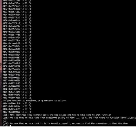
      8. To see which function called which function and so on till the current function- use ‘backtrace (bt)’ or ‘info stack’ or ‘where


      :

      :

      :


      10. To see the frame info of the latest stack frame from above- info frame


Now,

ESP is the current stack pointer. EBP is the base pointer for the current stack frame.

When you call a function, typically space is reserved on the stack for local variables. This space is usually referenced via EBP (all local variables and function parameters are a known constant offset from this register for the duration of the function call.) ESP, on the other hand, will change during the function call as other functions are called, or as temporary stack space is used for partial operation results.


      We need to know who had called us and what were the parameters given to me (the current function)


      So, ebp+ 0 will give us the previous ebp

      We can know the ebp address from the info registers

      Usually the value of ebp in info registers (which is the current value of the ebp) will be same as the info frame since it will be pointing to the local variables of current function.

      Now, ebp + 4 contains the return instruction where we have come from

      Example: 


      To see the above output to print 10 addresses, in hexadecimal format and in word length(.ie. 4 bytes, 8 bytes, …):

      Example:


      In that example, we see who has called us is this:


      In example, we can tell that the current function has been called from connect() function using:


      Now, we can do disassemble connect+176:


      So, we see that the instruction before 176 has a function call to mystrcpy()