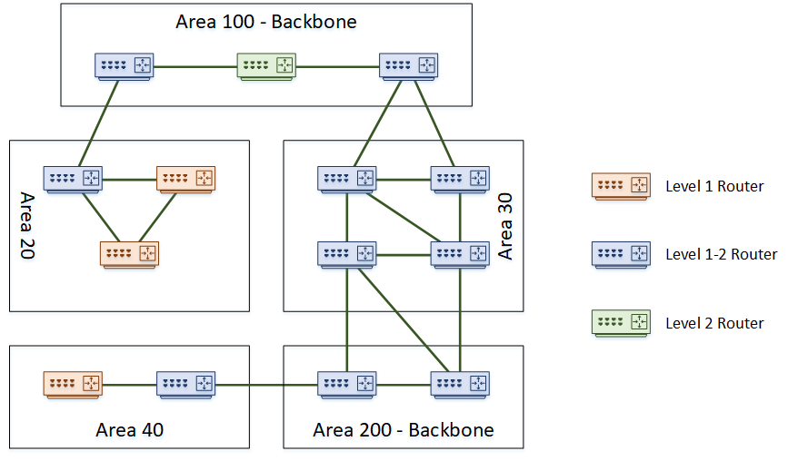
Level 1 routers will only share routing information with other Level 1 routers. This makes them stub routers. In the topology above, area 40 is a stub area. Routing within an area is Level 1 Routing.
Level 2 routers will only share routing information with other level 2 routers. These routers track routing information between areas. This is Level 2 Routing.
Level 1-2 routers are special, as they take part in both level 1 and level 2 routing. They connect areas together, which makes them the perfect place to use summarization. These routers maintain a separate database for level 1 and level 2 routes.
Areas can connect to each other, or a dedicated backbone area could be used for transport. Backbones consist of routers that do level 2 routing, including level 1-2 routers. They won’t have hosts or Level 1 routers connected.
A small network does not need to have a backbone at all. It can start as a single area with only level 1 routers. As an alternative, it can be all level 1-2 routers, to make it easier to add a backbone later.
A domain is an entire IS-IS system under common administration. This is like the concept of an Autonomous System in BGP.

The ultimate repository and knowledge house of Networking- Switches, Routers, Routing protocols, QoS, ASICs, Cisco, Arista networks
Tuesday 7 July 2020
Friday 19 June 2020
ISIS Series- Part 3: ISIS Areas
Like OSPF, IS-IS uses areas. Areas can be either a backbone area, or normal area. To support this concept, a router may be one of the following types:
- Level 1 – A router in a normal area that does not connect to another area
- Level 1-2 – A router in a normal or backbone area that connects different areas
- Level 2 – A backbone router that does not connect to other areas
The topology below shows an example of a network with several areas.
There are a few interesting points in this topology. Notice that the backbone area is not restricted to being ‘area 0’ like in OSPF. In IS-IS, any area number can be the backbone. Also notice that it is possible to partition the backbone. In this topology, both area 100 and area 200 are the backbone.
A further point of interest is that area boundaries are not on the routers themselves. Rather the area boundaries are between routers. This is different to OSPF, where an ABR or ASBR router is the boundary.
Saturday 9 May 2020
ISIS Series- Part 2: ISIS Components
As the history of IS-IS is in the OSI stack, some of the components are a bit different to what we’re used to in the TCP/IP world. Let’s clear up a few of the terms.
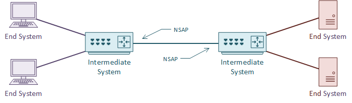
An IS is an Intermediate System. This is the ISO name for a router, and how IS-IS gets its name. It is communication between intermediate systems, or routers.
An ES is an End System. This is a device on the network, such as a server or workstation. In the original specification, an ES would take part in IS-IS. It would have no need for DHCP or FHRP, as it would already have a local routing table.
CLNS (Connection-Less Network Service) is a network service in the OSI stack. CLNP (Connection-Less Network Protocol) is the protocol that implements CLNS. If you’re more familiar with TCP/IP, this feels unusual. TCP/IP does not separate the service and the protocol in this way. This will make more sense with time.
An NSAP is a Network Service Access Point. This is a layer-3 address, for CLNS packets. This is like an IP address in the TCP/IP stack. IS-IS uses NSAP addresses for communication, not IP addresses. Again, this will make more sense as we go through the article.
TLV
TLV, or Type Length Value are the payload fields in IS-IS. The TLV fields carry routing information. IS-IS does not care what goes in these fields, which makes it protocol agnostic. This is a bit like shipping containers; The ship doesn’t care what’s in the containers.
IS-IS uses CLNS for transport. Each router has an NSAP address for sending and receiving link state information. The link state information may contain several TLV fields.
It is common to put IP routing information into the TLV’s. But any sort of data can be in there. It’s up to the receiving router to know what to do with the information.
Metric
Like OSPF, IS-IS uses cost as a metric. The specification says that this can be either a wide or narrow value. Cisco routers only support the wide metric. The narrow metric is not suitable for MPLS Traffic Engineering. The wide metric uses 24 bits for the link metric, and 32 bits for the path metric.
All links have a cost of 10 by default. This means that in a default implementation, hop-count forms the metric. It is up to the network designer to select a more suitable cost scheme.
Sunday 12 April 2020
ISIS Series- Part 1: Introduction to ISIS
IS-IS, or Intermediate System to Intermediate System, is an open standard routing protocol. ISO published the standard as a way to route datagrams as part of their OSI stack. IETF later republished the standard, and added IP route support.
There are a lot of similarities between IS-IS and OSPF. For one, both are link state routing protocols, meaning that they both build a ‘map’ of the network. They both flood link state data through the network, and build a Link State Database (LSDB). Also, they both run Diikjastra’s algorithm on the LSDB to compute shortest paths.
So, if it’s like OSPF, why use it at all? Why not use OSPF instead? Well, there are two massive strengths to IS-IS. The first is it’s scalability. It’s much easier to build large networks with IS-IS than it is with OSPF. This makes it a common choice with service providers for their infrastructure.
The second strength is its agnostic approach to the data it carries. IS-IS carries a payload of reachability data, but for the most part it doesn’t care what’s in the payload. This is what makes it useful for protocols such as FabricPath. In contrast, OSPF carries IP routes only. When IPv6 came along, it required a whole new version of OSPF (OSPFv3) to carry the IPv6 routes. No such issue in IS-IS.
Thursday 12 March 2020
Network Topologies- In context of DC
Data centers are crucial components in the functioning of modern businesses. These facilities house large amounts of data and computing resources that are critical for organizations to deliver their services. The architecture of a data center is of utmost importance in ensuring that these resources are accessible, secure, and reliable. One key aspect of data center architecture is network topology, which refers to the way in which the components of a network are arranged.
There are several network topologies that can be used in a data center, each with its own advantages and disadvantages. In this blog post, we'll explore some of the most common topologies and their applications.
Bus Topology
A bus topology consists of a single cable that connects all the devices in a network. Each device is connected to the cable through a T-connector, which splits the cable's signal. This topology is easy to implement and is cost-effective, but it can become slow and unreliable as the number of devices on the network increases. In a data center context, a bus topology is not typically used as it does not scale well.
Star Topology
A star topology consists of a central device, usually a switch or a hub, that connects to all the devices in the network through individual cables. This topology is easy to install, and faults are easy to isolate, making it a popular choice in data center architecture. However, it can be expensive to implement as it requires a large number of cables.
Ring Topology
A ring topology consists of devices that are connected to one another in a circular fashion. Each device is connected to two other devices, creating a ring. Data is transmitted in one direction around the ring, and each device repeats the signal to the next device. This topology is reliable and efficient but can be expensive to implement, and faults can be difficult to isolate.
Mesh Topology
A mesh topology consists of devices that are connected to one another through multiple paths. This topology is highly resilient and fault-tolerant as data can be rerouted if a path fails. It is also highly scalable and can accommodate a large number of devices. However, it can be expensive to implement, and the complexity of the network can make troubleshooting difficult.
Hybrid Topology
A hybrid topology is a combination of two or more topologies. For example, a data center might use a star topology for its access layer and a mesh topology for its core layer. This approach allows for greater flexibility in designing the network to meet specific requirements.
In conclusion, selecting the right network topology is critical for a data center's success. Each topology has its own strengths and weaknesses, and choosing the appropriate topology depends on factors such as scalability, reliability, cost, and ease of maintenance. Ultimately, a well-designed network topology can ensure that a data center functions efficiently, securely, and reliably, meeting the demands of modern businesses.
Subscribe to:
Posts (Atom)