Saturday 9 May 2020

ISIS Series- Part 2: ISIS Components


As the history of IS-IS is in the OSI stack, some of the components are a bit different to what we’re used to in the TCP/IP world. Let’s clear up a few of the terms.


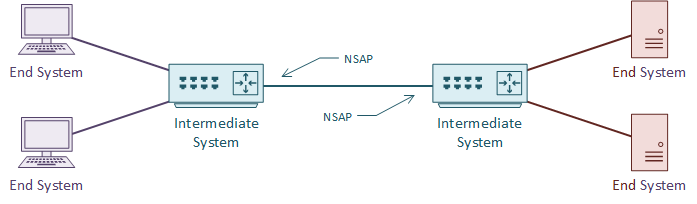
An IS is an Intermediate System. This is the ISO name for a router, and how IS-IS gets its name. It is communication between intermediate systems, or routers.

An ES is an End System. This is a device on the network, such as a server or workstation. In the original specification, an ES would take part in IS-IS. It would have no need for DHCP or FHRP, as it would already have a local routing table.

CLNS (Connection-Less Network Service) is a network service in the OSI stack. CLNP (Connection-Less Network Protocol) is the protocol that implements CLNS. If you’re more familiar with TCP/IP, this feels unusual. TCP/IP does not separate the service and the protocol in this way. This will make more sense with time.

An NSAP is a Network Service Access Point. This is a layer-3 address, for CLNS packets. This is like an IP address in the TCP/IP stack. IS-IS uses NSAP addresses for communication, not IP addresses. Again, this will make more sense as we go through the article.


TLV


TLV, or Type Length Value are the payload fields in IS-IS. The TLV fields carry routing information. IS-IS does not care what goes in these fields, which makes it protocol agnostic. This is a bit like shipping containers; The ship doesn’t care what’s in the containers.

IS-IS uses CLNS for transport. Each router has an NSAP address for sending and receiving link state information. The link state information may contain several TLV fields.

It is common to put IP routing information into the TLV’s. But any sort of data can be in there. It’s up to the receiving router to know what to do with the information.


Metric


Like OSPF, IS-IS uses cost as a metric. The specification says that this can be either a wide or narrow value. Cisco routers only support the wide metric. The narrow metric is not suitable for MPLS Traffic Engineering. The wide metric uses 24 bits for the link metric, and 32 bits for the path metric.

All links have a cost of 10 by default. This means that in a default implementation, hop-count forms the metric. It is up to the network designer to select a more suitable cost scheme.

Sunday 12 April 2020

ISIS Series- Part 1: Introduction to ISIS

IS-IS, or Intermediate System to Intermediate System, is an open standard routing protocol. ISO published the standard as a way to route datagrams as part of their OSI stack. IETF later republished the standard, and added IP route support.

There are a lot of similarities between IS-IS and OSPF. For one, both are link state routing protocols, meaning that they both build a ‘map’ of the network. They both flood link state data through the network, and build a Link State Database (LSDB). Also, they both run Diikjastra’s algorithm on the LSDB to compute shortest paths.

So, if it’s like OSPF, why use it at all? Why not use OSPF instead? Well, there are two massive strengths to IS-IS. The first is it’s scalability. It’s much easier to build large networks with IS-IS than it is with OSPF. This makes it a common choice with service providers for their infrastructure.

The second strength is its agnostic approach to the data it carries. IS-IS carries a payload of reachability data, but for the most part it doesn’t care what’s in the payload. This is what makes it useful for protocols such as FabricPath. In contrast, OSPF carries IP routes only. When IPv6 came along, it required a whole new version of OSPF (OSPFv3) to carry the IPv6 routes. No such issue in IS-IS.

Thursday 12 March 2020

Network Topologies- In context of DC


Data centers are crucial components in the functioning of modern businesses. These facilities house large amounts of data and computing resources that are critical for organizations to deliver their services. The architecture of a data center is of utmost importance in ensuring that these resources are accessible, secure, and reliable. One key aspect of data center architecture is network topology, which refers to the way in which the components of a network are arranged.

There are several network topologies that can be used in a data center, each with its own advantages and disadvantages. In this blog post, we'll explore some of the most common topologies and their applications.

Bus Topology


A bus topology consists of a single cable that connects all the devices in a network. Each device is connected to the cable through a T-connector, which splits the cable's signal. This topology is easy to implement and is cost-effective, but it can become slow and unreliable as the number of devices on the network increases. In a data center context, a bus topology is not typically used as it does not scale well.

Star Topology


A star topology consists of a central device, usually a switch or a hub, that connects to all the devices in the network through individual cables. This topology is easy to install, and faults are easy to isolate, making it a popular choice in data center architecture. However, it can be expensive to implement as it requires a large number of cables.

Ring Topology


A ring topology consists of devices that are connected to one another in a circular fashion. Each device is connected to two other devices, creating a ring. Data is transmitted in one direction around the ring, and each device repeats the signal to the next device. This topology is reliable and efficient but can be expensive to implement, and faults can be difficult to isolate.

Mesh Topology


A mesh topology consists of devices that are connected to one another through multiple paths. This topology is highly resilient and fault-tolerant as data can be rerouted if a path fails. It is also highly scalable and can accommodate a large number of devices. However, it can be expensive to implement, and the complexity of the network can make troubleshooting difficult.

Hybrid Topology


A hybrid topology is a combination of two or more topologies. For example, a data center might use a star topology for its access layer and a mesh topology for its core layer. This approach allows for greater flexibility in designing the network to meet specific requirements.

In conclusion, selecting the right network topology is critical for a data center's success. Each topology has its own strengths and weaknesses, and choosing the appropriate topology depends on factors such as scalability, reliability, cost, and ease of maintenance. Ultimately, a well-designed network topology can ensure that a data center functions efficiently, securely, and reliably, meeting the demands of modern businesses.

Wednesday 19 February 2020

Wireshark Series: Part 3- TCP and UDP


• Transmission Control Protocol (TCP):

○ TCP makes sure that the data goes to destination in a reliable manner
○ TCP sends data b/w ports which range from 0 to 65535
§ Ports from 1- 1023 are called Standard Ports. These can be Port 80 for HTTP
§ Ports 1024- 65535 are called ephimeral ports. These are randomly selected when a device needs to find an open port. Both the destination and the client need to know what port the other one is listening on to be able to transmit data between them
○ TCP communications start with a handshake to ensure both source and destination are up and ready to communicate. It checks the open port and send the sequence number so that the data is sent reliably.
○ To establish a TCP session the sending and receiving TCP applications us a process called the three way handshake.
STEP 1 - The sender send a SYN packet to begin establishment of the session. It waits
STEP 2 - The receiver replies with an ACK packet to acknowledge the SYN that it received and also sends a SYN packet.
STEP 3 - The sender sends an ACK to acknowledge receipt of the SYN from the receiver.
The connection is now set up and data transfer can commence.
○ Now to terminate a connection you can do it the graceful way which is a four way process. Lets assume that the sender is finished with data transmission and now wants to end the session, similar to logging off an application.
STEP 1 - The sender sends a FIN packet and waits for a reply
STEP 2 - The receiver send and ACK packet
STEP 3 - The receiver also sends a FIN packet
STEP 4 - The sender sends an ACK packet and the session is closed.
○ You can also do an abrupt termination by just sending a RST packet from either sender or transmitter and the session ends abruptly. For example if you are using telnet CTRL-D will send a RST to close the session.
○ In Wireshark,
§

§
§ First, we see Source Port which was used to transmit the packet
§ Second, we have Destination Port to where the packet will be transmitted
§ Next, we have the Sequence Number  makes sure that none of the TCP segments are missing and it shows the current segement no.
§ Acknowledgement Number is the sequence number of the next packet
§ Flags are after this and they can be:
□ URG for Urgent
□ PSH for push
□ RST for Reset. If the connection is halted all of a sudden by accident, then TCP  will reset the connection and stop all communications
□ SYN
□ FIN for finished
(Here, we have a FIN, ACK packet going on, so we know that this is a packet that includes acknowledgement. Also, because FIN=1, it means that it is also a finishing packet)
§ Below Flag, we have the Window Size. Window Size is the size of the TCP receiver buffer (in bytes).
§ After that, we have the Checksum

• User datagram Protocol (UDP):
○ It is a connectionless protocol used for faster transmissions
○ It does not have a start handshake and a cutoff handshake like TCP. Because of this, it helps other protocols transfer data at a much faster pace
○ In Wireshark,
§
§ It is a super small packet
○ It has 4 parts:
§ Source Port (here: 33233)
§ Destination port (here: 59329)
§ Length (in bytes)
§ Checksum


Wednesday 12 February 2020

WireShark Series: Part 2- ARP and IP

• Address Resolution Protocol (ARP):
○ First, inorder to send TCP/IP , the computer first sends out an ARP request
○ It means, the computer wants to send to another IP address but it doesnt know the MAC address. The other computer will respond back by telling its MAC address
○ ARP is sent as an broadcast.
○ ARP format is as below:

§ Hardware Type: Ethernet is type 1
§ Protocol Type: This could be IPv4 which will be listed as 0X0800
§ Hardware Address Length: This could be like a number 6 for Ethernet
§ Protocol Address Length: This is number 4 for IPv4 
§ Operation: Tells the operation that the sender is doing. 1 stands for ARP request and 2 stands for ARP reply
§ Then , we have senders hardware address and the protocol address
§ Lastly, we have target's hardware and protocol address
○ In Wireshark, 

§ We will see that the MAC address listed under Target MAC is bunch of zeros  since the sender doesnt know the MAC and is asking for it using ARP request (1)
○ ARP helps to resolve the MAC address so that we can then go onto next layer
○ It is a Layer 2 protocol. But, it has Layer 3 information(IP address)
○ Each device has an ARP table and both the source and destination will add each other to its ARP table entry
• Internet Protocol:
○ We can denote the IP and net mask using cidr notation also. (cidr= classless interdomain routing notation)
○ For eg., 192.168.0.1  with netmaskof 255.255.0.0 can be represented using cidr notation as 192.168.0.1 /16
○ In Wireshark,
§ Use the IPv4 Packet Format that we saw previously

§ IP version is 4
§ IP header length is 20 (here, no padding + option)
§ Total length is 40 (header +data)
§ ID is the ID number for the actual packet (here: 18242). So, we know exactly which packet we are using
§ Flag will be used if the packet is part of a larger sequence of packets
§ Here, Don't Fragment = 1 means no other fragments.
§ TTL (Time to Live ) here is 128. It is used to prevent the packet from looping around and around on the internet
§ Protocol for this packet is TCP
§ Then we have Source IP, Destination IP and any Options
○ The fragment size depends upon the MTU (Maximum transmission Unit of the layer-2 protocol). For eg., if we use ethernet, the maximum packet size is 1500 bytes. So, the IP fragmentation would occur if the IP packet was over 1500.
§ In above example, we see that More is set to 0 since there are no fragments along with it. Also, in a series, if this was the last packet even then this value will be zero as it is the last packet and no more packets are after this
§ The Fragment Offset gives details about where the fragment falls in the series