Routing Protocols used in Data centers and advantage/disadv of OSPF (Link State) with BGP:
Oversubscription:
- Spine Layer must have 1:1 Oversubscription ratio since it becomes non-blocking
- Leaf Layer can have x:1 oversubscription Ratio since one leaf is connected to all the Spines
- NOTE: Oversubscription at the leaf node is controlled by maintaining a ratio of uplinks to downlinks. A 2:1 oversubscription ratio would imply that twice as many ports are used for servers(downlink) than for uplinks.
Network Design Considerations: The number of spine nodes required for a given design will depend on a few factors including:
- Number of Compute/Storage Racks: All leaf uplinks must be accommodated by the spine nodes depending on the oversubscription ratio at the leaf. For eg, if leaf has 3:1 ratio , then, for 64-port leaf device, 16 links will be uplink and 48 will be connected to servers
- Controlling Fault Domains: Provisions must be made to contain control plane failures to minimize impact on capacity as well as prevent the spread of control plane poisoning.
Network Protocol Considerations:
OSPF (Link State IGP):
- Since OSPF generates link state updates for a single event which must be flooded to all the neighbors, the devices must have powerful control plane processors
- Single Pass Spine: it is critical that no single leaf node shall be a transit path for any other leaf node. A link-state IGP can infact introduce momentary leaf-transit scenarios during protocol state-transitions. Such transitive traffic patterns temporarily disrupt our pre- defined oversubscription ratios and can be very hard to characterize given how short-lived these events may be.
- Unnecessary N-Way Routes: Each spine node will have a direct point-to-point interfaces to each leaf node. We expect adjacencies to be established between each spine node and every leaf node. Now consider a scenario where ospf adjacency has not yet been established between spine-1 and leaf-1 or we have a faulty cable between these devices. In this state, spine-1 learns about leaf-1’s host network through every other leaf node.EOS offers a ‘maximum-paths’ feature to limit the number of n-way IGP routes that get installed on a spine device. In smaller deployments where a link-state IGP is adequate, this feature can be used. However, we can prevent n-way routes from being installed altogether by considering an alternative design and routing protocol.
BGP:
- Consider a design where the spine nodes are configured to be in a single BGP autonomous system while each leaf-node is assigned a unique AS number. The private AS range of 64512-65535 is available for such designs allowing for upto 1023 AS numbers to be assigned within a single pod.
- This approach addresses many of the undesirable side-effects seen in a typical link-state environments. In particular, BGP’s built-in loop suppression capabilities prevent unnecessary control plane churn. With this design, we are able to create a ‘single-pass’ spine, eliminate unnecessary n-way routes and significantly reduce the amount of control plane traffic that would otherwise result when nodes are rebooted or upgraded.
- Also, in BGP, the control plane activity is contant whereas in OSPF there is high control plane activity during link state changes
Conclusion:
- EOS platforms have powerful control plane architectures and can support both OSPF and BGP topologies very effectively. Although EOS has incorporated additional features to support large OSPF CLOS designs, BGP is better suited to handle large ECMP designs with it’s native loop-suppression and policy framework.

The ultimate repository and knowledge house of Networking- Switches, Routers, Routing protocols, QoS, ASICs, Cisco, Arista networks
Sunday 4 November 2018
Routing Protocols used in Data centers and advantage/disadv of OSPF (Link State) with BGP


Thursday 27 September 2018
Large Scale Data-Center Networks- Part 2
2. Edge Services and Border Leafs
For two-tier and three-tier data center topologies, the role of the border leaf in the network is to provide external connectivity to the data center site. In addition, since all traffic enters and exits the data center through the border leaf switches, they present the ideal location in the network to connect network services like firewalls, load balancers, and edge VPN routers. The border leaf switches connect to the WAN edge devices in the network to provide external connectivity to the data center site. As a design principle, two border leaf switches are recommended for redundancy. The WAN edge devices provide the interfaces to the Internet and DCI solutions. For DCI, these devices function as the Provide Edge (PE) routers, enabling connections to other data center sites through WAN technologies like Multiprotocol Label Switching (MPLS) VPN and Virtual Private LAN Services (VPLS). The Brocade validated design for DCI solutions is discussed in a separate validated design document.
There are several ways that the border leafs connect to the data center site. In three-tier (super-spine) architectures, the border leafs are typically connected to the super-spines as depicted in Figure 2 (3tier) below. In two-tier topologies, the border leafs are connected to the spines as depicted in Figure 1 (2tier) above. Certain topologies may use the spine as border leafs (known as a border spine), overloading two functions into one. This topology adds additional forwarding requirements to spines—they need to be aware of the tenants, VNIs, and VXLAN tunnel encapsulation and de-encapsulation functions.
3. Optimized 5-Stage Layer 3 Clos Topology (Three-Tier)
Multiple PoDs based on leaf-spine topologies can be connected for higher scale in an optimized 5-stage folded Clos (three-tier) topology. This topology adds a new tier to the network, known as a super-spine. This architecture is recommended for interconnecting several EVPN VXLAN PoDs. Super-spines function similar to spines: BGP control-plane and IP forwarding based on the outer IP header in the underlay network. No endpoints are connected to the super-spine. Figure 2 shows four super-spine switches connecting the spine switches across multiple data center PoDs.
The connection between the spines and the super-spines follows the Clos principles:
- Each spine connects to all super-spines in the network.
- Neither spines nor super-spines are interconnected with each other.
FIGURE 2 Optimized 5-Stage L3 Clos Topology

FOR MORE INFORMATION ON Underlay Routing, see:
- http://www.brocade.com/content/html/en/brocade-validated-design/brocade-ip-fabric-bvd/GUID-2B84EB71-9AF7-40B0-9E17-5A460F53AB1A.html
- http://www.cisco.com/c/en/us/products/collateral/switches/nexus-7000-series-switches/white-paper-c11-737022.html
For more information on Network Virtualization with BGP EVPN, see:
For information on validated Designs:
Sunday 23 September 2018
Large Scale Data-Center Networks- Part 1
1. Leaf-Spine Layer 3 Clos Topology (Two-Tier):
- The leaf-spine topology has become the de facto standard for networking topologies when building medium- to large-scale data center infrastructures. The leaf-spine topology is adapted from Clos telecommunications networks.
- The IP fabric within a PoD resembles a two-tier or 3-stage folded Clos fabric.
- The two-tier leaf-spine topology is shown in Figure 1.
- The bottom layer of the IP fabric has the leaf devices (top-of-rack switches), and the top layer has spines.
- The role of the leaf is to provide connectivity to the endpoints in the data center network. These endpoints include compute servers and storage devices as well as other networking devices like routers, switches, load balancers, firewalls, and any other physical or virtual networking endpoints. Because all endpoints connect only to the leaf, policy enforcement, including security, traffic-path selection, QoS marking, traffic policing, and shaping, is implemented at the leaf. More importantly, the leafs act as the anycast gateways for the server segments to facilitate mobility with the VXLAN overlay.
- The role of the spine is to provide connectivity between leafs. The major role of the spine is to participate in the control-plane and data-plane operations for traffic forwarding between leafs.
- The spine devices serve two purposes: BGP control plane (route reflectors for leaf or eBGP peering with leaf) and IP forwarding based on the outer IP header in the underlay network. Since there are no network endpoints connected to the spine, tenant VRFs or VXLAN segments are not created on spines. Their routing table size requirements are also very light to accommodate just the underlay reachability. Note that all spine devices need not act as BGP route reflectors; only selected spines in the spine layer can act as BGP route reflectors in the overlay design.
1.1. As a design principle, the following requirements apply to the leaf-spine topology:
- Each leaf connects to all spines in the network through 40-GbE links.
- Spines are not interconnected with each other.
- Leafs are not interconnected with each other for data-plane purposes. (The leafs may be interconnected for control-plane operations such as forming a server-facing vLAG.)
- The network endpoints do not connect to the spines.
This type of topology has the predictable latency and also provides the ECMP forwarding in the underlay network. The number of hops between two leaf devices is always two within the fabric. This topology also enables easier scale out in the horizontal direction as the data center expands and is limited by the port density and bandwidth supported by the spine devices.
This validated design recommends the same hardware in the spine layer. Mixing different hardware is not recommended.
1.2. IP Fabric Infrastructure Links:
All fabric nodes—leafs, spines, and super-spines—are interconnected with Layer 3 interfaces. In the validated design,
- 40-GbE links are used between the fabric nodes.
- All these links are configured as Layer 3 interfaces with /31 IPv4 address. For a simple 3-stage fabric, IP unnumbered interfaces can be used. We do not recommend a mix of unnumbered and numbered interfaces within a fabric. Also, for a 5-stage IP fabric, numbered interfaces are highly recommended.
- The MTU for these links is set to jumbo MTU. This is a requirement to handle the VXLAN encapsulation of Ethernet frames.
1.3.1 Server-Facing Links (Individual Leaf/ToR):
The server-facing or access links are on the leaf nodes. In the validated design,
- 10-GbE links are used for server-facing VLANs.
- These links are configured as Layer 2 trunks with associated VLANs.
- The MTU for these links is set to the default: 1500 bytes.
- Spanning tree is disabled.

1.3.2 Server-Facing Links (vLAG Pair/ToR):
vLAG configuration involves three steps:
- Node ID configuration on the pair of devices.
- Inter-switch links or ISL configuration on both devices.
- Configuring the server-facing port channels and adding the required VLANs on them.
See below for more info on configurations: http://www.brocade.com/content/html/en/brocade-validated-design/brocade-ip-fabric-bvd/GUID-F54693FB-7866-43B5-8610-71F2B2B85ECA.html
1.4 Leaf-Spine L3 Clos Topology:

Spanning tree must be enabled if there are Layer 2 switches/bridges between a leaf and servers.
Friday 7 September 2018
Arista MLAG (Multi Chassis Link Aggregation)
MLAG (Multi Chassis Link Aggregation)
Topology:
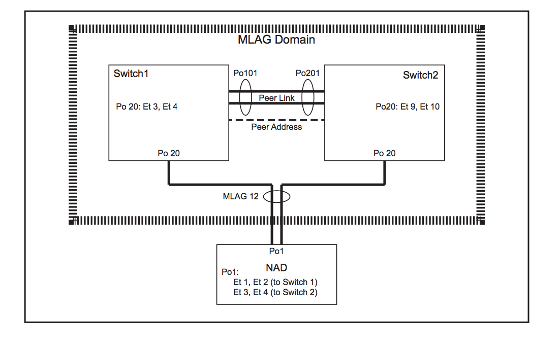
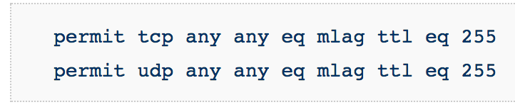
- On both switches, ensure that the control plane ACL configuration is compatible with MLAG. These two rules exist in the default-control-plane-acl configuration. You can verify with the command: show ip access-lists default-control-plane-acl
- Create port-channel for the peer-link
- They can be different number as shown in above picture
- switch1# config t
switch1(conf)#interface eth1-2
switch1(config-if-Et1-2)# channel-group 101 mode active
switch1(config)# interface port-channel 101
switch1(config-if-Po101)# switchport mode trunk - Similarly, configure on Switch 2 as well with the desired port-channel number
- Note: It is recommended, for redundancy reasons to use a port-channel. The peer link is recommended to be at least a two port port-channel to avoid having a single point of failure.
- On both switches, create a VLAN with an unused vlan-id for the MLAG peers to communicate.
- switch1(conf)#vlan 4094
switch1(config-vlan-4094)# trunk group mlagpeer
switch1(config-vlan-4094)# interface port-channel 101
switch1(config-if-Po101)# switchport trunk group mlagpeer
switch1(config-if-Po101)# exit
switch1(conf)#no spanning-tree vlan 4094 - Use exactly same config on Switch 2
- Note: The trunk group names for the peer VLAN (mlagpeer in the above example) should be configured to be the same on both switches. In order to successfully establish an MLAG association, the configuration for vlans and vlan trunk groups must be identical
- Assigning VLAN4094 and Port-Channel10 to trunk group ‘mlagpeer’ prevents VLAN4094 from being carried on any trunk other than Po10. This allows you to safely disable Spanning-Tree on VLAN4094
- Another option other than using trunk groups is to prune Vlan 4094 from all other Vlans which is cumbersome
- Configure the SVI for peer-to-peer communication:
- On Switch 1:
switch1(conf)#int vlan 4094
switch1(config-if-Vl4094)# ip address 10.0.0.1/30
switch1(config-if-Vl4094)#no autostate
- On Switch 2:
switch2(conf)#int vlan 4094
switch2(config-if-Vl4094)# ip address 10.0.0.2/30
switch2(config-if-Vl4094)#no autostate
- Check for connectivity by pinging each other
- Note: The The local and peer addresses must be located on the same IP address subnet. Autostate should be disabled on the SVI configured as the local interface.
- Configure the MLAG peering on both the switches:
- On Switch 1:
switch1(config)#mlag
switch1(config-mlag)#local-interface vlan 4094
switch1(config-mlag)#peer-address 10.0.0.2
switch1(config-mlag)#peer-link port-channel 101
switch1(config-mlag)#domain-id mlag1
- On Switch 2:
switch2(config)#mlag
switch2(config-mlag)#local-interface vlan 4094
switch2(config-mlag)#peer-address 10.0.0.1
switch2(config-mlag)#peer-link port-channel 201
switch2(config-mlag)#domain-id mlag1
- Verify MLAG operation:
- Check if the MLAG is up by running (config)#show mlag and checking if the MLAG STATUS is shown as ACTIVE
Troubleshooting: MLAG Status not becoming ACTIVE:
- Check if the configuration is similar on both the peers: domain-id, vlan, ip address in same subnet, trunk group name.
- Verify that Spanning tree disabled on Vlan
- Check if lower layer layers are up and not errDisabled. If yes, then, shut and unshut to bring them up
Troubleshooting: MLAG Status ACTIVE but INCONSISTENT:
- Use this command to see the inconsistencies: (config)#show mlag config-sanity
- To check for inconsistencies in MLAG (even though MLAG is active):
- Check if different Vlans are configured on the peers that allow the MLAG port-channel. (eg: On switch 1, po10 is allowed on Vlan 4094, default, Vlan 2 and Vlan3; whereas on Switch 2 , po10 is allowed on Vlan 4094, default)
- VLANs must be created on each MLAG peer. The primary MLAG peer does not communicate VLAN information to the secondary. So, Take care to configure VLANs and port settings (Port-specific bridging configuration comes from the switch where the port physically lives. This includes switchport access vlan, switchport mode, trunk allowed vlans, trunk native vlan, and switchport trunk groups) identically on both MLAG peers
- (config)#show vlan —> check if other vlans have po10 and also if u can see all peer interfaces as pE
- Verify if same EOS versions on both the peers
7) Configure MLAG Services:
- Note: The mlag identification number does not have to match the port-channel number
- Note: The port-channel numbers grouped in an MLAG must match, they cannot be two different values.
- Note: A port-channel in an MLAG can have multiple members.
- In short: Port channels configured as an MLAG must have identical port channel numbers. Although the MLAG ID is a distinct parameter from the port channel number, best practices recommend assigning the MLAG ID to match the port channel number. The following example does not follow this convention to emphasize the parameters that are distinct (see that po20 has been used but mlag id is 12...though not recommended).
- These Switch1 commands bundle Ethernet interfaces 3 and 4 in port channel 20, then associate that port channel with MLAG 12.
switch1(config)#interface ethernet 3-4
switch1(config-if-et3-4)#channel-group 20 mode active switch1(config-if-et3-4)#interface port-channel 20 switch1(config-if-po20)#mlag 12
switch1(config-if-po20)#exit
switch1(config)#
- These Switch2 commands bundle Ethernet interfaces 9 and 10 in port channel 15, then associate that port channel with MLAG 12.
- Note that same mlag id and same port-channel number (for downstream device) [here: mlag 12 and po20] should be used on both the peers
switch2(config)#interface ethernet 9-10 switch2(config-if-et9-10)#channel-group 15 mode active switch2(config-if-et9-10)#interface port-channel 20 switch2(config-if-po20)#mlag 12
switch2(config-if-po20)#exit
switch2(config)#
- These commands configure the port channels that attach to the MLAG on network attached device:
- Note that on the device, there is no MLAG specific configuration. It is configured as a regular port channel
NAD(config)#interface ethernet 1-4
NAD(config-if-Et1-4)#channel-group 1 mode active
NAD(config-if-Et1-4)#exit
NAD(config)#
- FOR ADVANCED TOPOLOGY CONFIGURATION, see the EOS Config Manual (there is an example in that with full config)
- FOR more details on MLAG, see EOS Config Manual
- To view any syslog messages, you will need to change MLAG level to debugging: Switch(config)# logging level mlag 7
- Troubleshooting and Debugging Mlag- Useful commands:
- Show mlag detail
- Show mlag interface detail
- Show mlag tunnel counter detail
- Show lacp nei
- Show lldp nei
- Trace commands
- Cd /var/log/messages
- Cd /var/log/agents
Subscribe to:
Posts (Atom)