MLAG (Multi Chassis Link Aggregation)
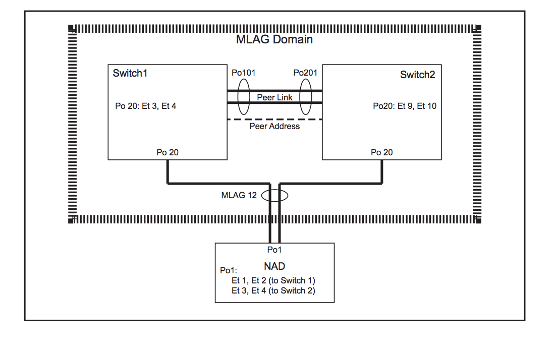
Topology:
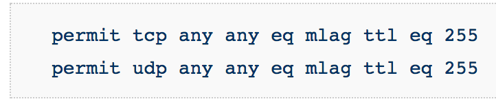
- On both switches, ensure that the control plane ACL configuration is compatible with MLAG. These two rules exist in the default-control-plane-acl configuration. You can verify with the command: show ip access-lists default-control-plane-acl
- Create port-channel for the peer-link
- They can be different number as shown in above picture
- switch1# config t
switch1(conf)#interface eth1-2
switch1(config-if-Et1-2)# channel-group 101 mode active
switch1(config)# interface port-channel 101
switch1(config-if-Po101)# switchport mode trunk - Similarly, configure on Switch 2 as well with the desired port-channel number
- Note: It is recommended, for redundancy reasons to use a port-channel. The peer link is recommended to be at least a two port port-channel to avoid having a single point of failure.
- On both switches, create a VLAN with an unused vlan-id for the MLAG peers to communicate.
- switch1(conf)#vlan 4094
switch1(config-vlan-4094)# trunk group mlagpeer
switch1(config-vlan-4094)# interface port-channel 101
switch1(config-if-Po101)# switchport trunk group mlagpeer
switch1(config-if-Po101)# exit
switch1(conf)#no spanning-tree vlan 4094 - Use exactly same config on Switch 2
- Note: The trunk group names for the peer VLAN (mlagpeer in the above example) should be configured to be the same on both switches. In order to successfully establish an MLAG association, the configuration for vlans and vlan trunk groups must be identical
- Assigning VLAN4094 and Port-Channel10 to trunk group ‘mlagpeer’ prevents VLAN4094 from being carried on any trunk other than Po10. This allows you to safely disable Spanning-Tree on VLAN4094
- Another option other than using trunk groups is to prune Vlan 4094 from all other Vlans which is cumbersome
- Configure the SVI for peer-to-peer communication:
- On Switch 1:
switch1(conf)#int vlan 4094
switch1(config-if-Vl4094)# ip address 10.0.0.1/30
switch1(config-if-Vl4094)#no autostate
- On Switch 2:
switch2(conf)#int vlan 4094
switch2(config-if-Vl4094)# ip address 10.0.0.2/30
switch2(config-if-Vl4094)#no autostate
- Check for connectivity by pinging each other
- Note: The The local and peer addresses must be located on the same IP address subnet. Autostate should be disabled on the SVI configured as the local interface.
- Configure the MLAG peering on both the switches:
- On Switch 1:
switch1(config)#mlag
switch1(config-mlag)#local-interface vlan 4094
switch1(config-mlag)#peer-address 10.0.0.2
switch1(config-mlag)#peer-link port-channel 101
switch1(config-mlag)#domain-id mlag1
- On Switch 2:
switch2(config)#mlag
switch2(config-mlag)#local-interface vlan 4094
switch2(config-mlag)#peer-address 10.0.0.1
switch2(config-mlag)#peer-link port-channel 201
switch2(config-mlag)#domain-id mlag1
- Verify MLAG operation:
- Check if the MLAG is up by running (config)#show mlag and checking if the MLAG STATUS is shown as ACTIVE
Troubleshooting: MLAG Status not becoming ACTIVE:
- Check if the configuration is similar on both the peers: domain-id, vlan, ip address in same subnet, trunk group name.
- Verify that Spanning tree disabled on Vlan
- Check if lower layer layers are up and not errDisabled. If yes, then, shut and unshut to bring them up
Troubleshooting: MLAG Status ACTIVE but INCONSISTENT:
- Use this command to see the inconsistencies: (config)#show mlag config-sanity
- To check for inconsistencies in MLAG (even though MLAG is active):
- Check if different Vlans are configured on the peers that allow the MLAG port-channel. (eg: On switch 1, po10 is allowed on Vlan 4094, default, Vlan 2 and Vlan3; whereas on Switch 2 , po10 is allowed on Vlan 4094, default)
- VLANs must be created on each MLAG peer. The primary MLAG peer does not communicate VLAN information to the secondary. So, Take care to configure VLANs and port settings (Port-specific bridging configuration comes from the switch where the port physically lives. This includes switchport access vlan, switchport mode, trunk allowed vlans, trunk native vlan, and switchport trunk groups) identically on both MLAG peers
- (config)#show vlan —> check if other vlans have po10 and also if u can see all peer interfaces as pE
- Verify if same EOS versions on both the peers
7) Configure MLAG Services:
- Note: The mlag identification number does not have to match the port-channel number
- Note: The port-channel numbers grouped in an MLAG must match, they cannot be two different values.
- Note: A port-channel in an MLAG can have multiple members.
- In short: Port channels configured as an MLAG must have identical port channel numbers. Although the MLAG ID is a distinct parameter from the port channel number, best practices recommend assigning the MLAG ID to match the port channel number. The following example does not follow this convention to emphasize the parameters that are distinct (see that po20 has been used but mlag id is 12...though not recommended).
- These Switch1 commands bundle Ethernet interfaces 3 and 4 in port channel 20, then associate that port channel with MLAG 12.
switch1(config)#interface ethernet 3-4
switch1(config-if-et3-4)#channel-group 20 mode active switch1(config-if-et3-4)#interface port-channel 20 switch1(config-if-po20)#mlag 12
switch1(config-if-po20)#exit
switch1(config)#
- These Switch2 commands bundle Ethernet interfaces 9 and 10 in port channel 15, then associate that port channel with MLAG 12.
- Note that same mlag id and same port-channel number (for downstream device) [here: mlag 12 and po20] should be used on both the peers
switch2(config)#interface ethernet 9-10 switch2(config-if-et9-10)#channel-group 15 mode active switch2(config-if-et9-10)#interface port-channel 20 switch2(config-if-po20)#mlag 12
switch2(config-if-po20)#exit
switch2(config)#
- These commands configure the port channels that attach to the MLAG on network attached device:
- Note that on the device, there is no MLAG specific configuration. It is configured as a regular port channel
NAD(config)#interface ethernet 1-4
NAD(config-if-Et1-4)#channel-group 1 mode active
NAD(config-if-Et1-4)#exit
NAD(config)#
- FOR ADVANCED TOPOLOGY CONFIGURATION, see the EOS Config Manual (there is an example in that with full config)
- FOR more details on MLAG, see EOS Config Manual
- To view any syslog messages, you will need to change MLAG level to debugging: Switch(config)# logging level mlag 7
- Troubleshooting and Debugging Mlag- Useful commands:
- Show mlag detail
- Show mlag interface detail
- Show mlag tunnel counter detail
- Show lacp nei
- Show lldp nei
- Trace commands
- Cd /var/log/messages
- Cd /var/log/agents